Forum Replies Created
-
AuthorPosts
-
January 14, 2017 at 8:36 pm #21420
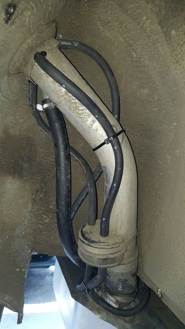
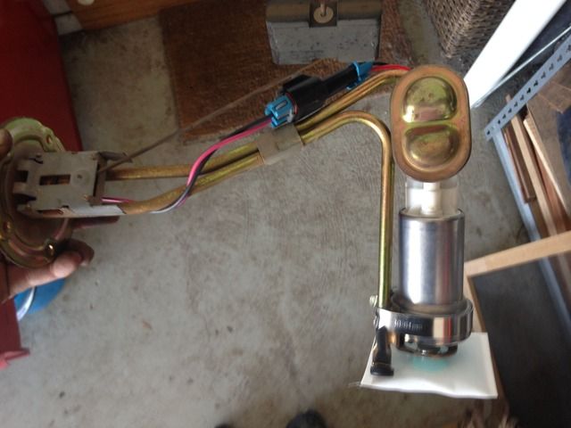
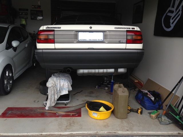
Operation Ghetto Booty is a success. After trying to get the 1/2″ hose onto a 5/8″ fitting for the tank overflow (thanks Autobarn!) I had some delays in getting the tank back in. Managed to get the correct hose from Enzed on Friday so smashed it back in today.
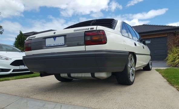
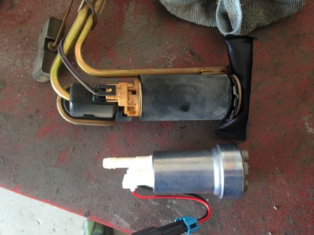
The Walbro 460 is very quiet, better than the stock pump for sure. Now has E85 compatible hoses for what it’s worth. Getting closer to the target “Dirty circa 1999-2001 Western Suburbs of Melbourne lapping Keilor Park Drive VN BT1 Bro” look I’m going for.
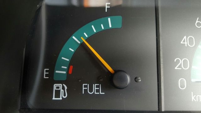
On a serious note it seems as though there’s no real need to change the fuel level sender output display on the guage. It doesn’t have the resolution it should at the lower end (i.e. with ~15L in the tank it showed a bit over 1/16 of a tank, but at 40L in the tank it showed just over 1/2, so no stress.)
Replaced all of the breather lines and what not.
Exactly 40L in,
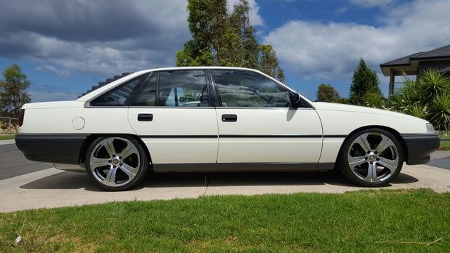
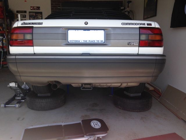
Starting to look alright
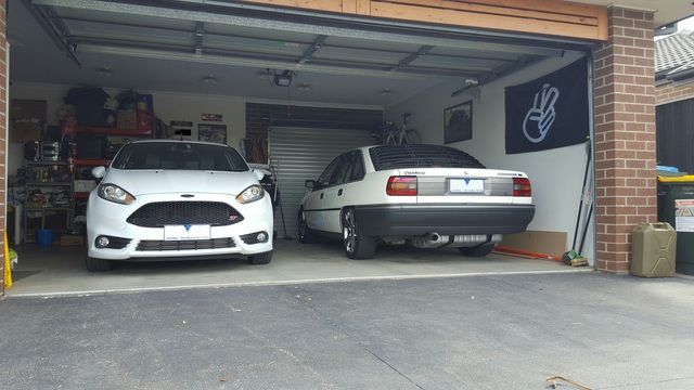
The toys in the shed for the night.
-
This reply was modified 7 years, 10 months ago by
![Profile photo of [TUFFVQ]](http://www.commodoresplus.com.au/wp-content/uploads/avatars/86/415b3c931a93cef3c2bc51efc23b2e0a-bpthumb.jpg) [TUFFVQ].
[TUFFVQ].
January 10, 2017 at 8:27 am #21384What they said.
Easiest and quickest way to learn – dive in and have a go. If you don’t go making wholesale changes in one go then you’re really not going to hurt an N/A engine…
January 9, 2017 at 9:20 am #21376Ordered a set of long shank aluminium carbides to help progress the manifold. Need to source some other items to port the runners themselves.
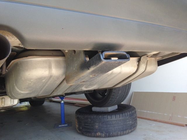
Started installing the 80L fuel tank into the car yesterday (operation ‘Ghetto Booty’). Faced some issues with being given the wrong size hose for the tank overflow line by the helpful attendant at the local parts store, as well as the VHT paint I applied deciding it didn’t want to stay on the tank meant I had to strip the tank (again!) and repaint it in VHT Caliper Paint rather than Quick Coat. I wasn’t that concerned as I didn’t really like the finish on the Quick Coat and the Caliper Paint is less metallic and looks more like I think it should.
Installed (Jammed) a Walbro 460 pump in as well while I was there. The tank came from an IRS car so I knew I was in for some modification to the support straps. Turns out the driver side strap bolts straight up, but the passenger side strap needs the diff-end attachment point modified – the IRS chassis uses a tab that goes into a slot on the chassis, where-as the live axle cars use a bolt. Cut that last 100mm off the 63L tank strap and weld it to the 80L strap to extend the effective mounting point by 80mm and you’re good to go. I also removed the 1200kg tow bar.
Haven’t finished the job yet as I ran out of time yesterday. Need to strip and paint the straps black and get some new 5/16″ line as the old ones are too short now. Hopefully finish it Tuesday or Thursday…
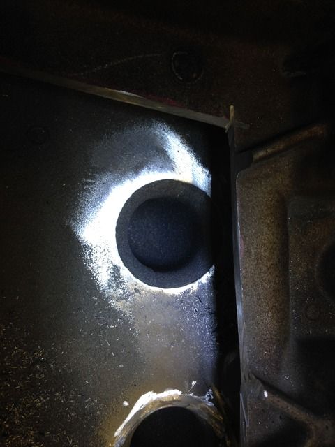
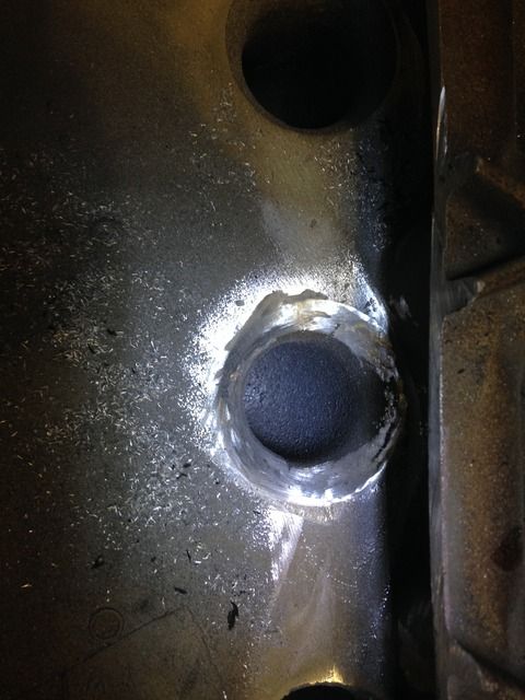
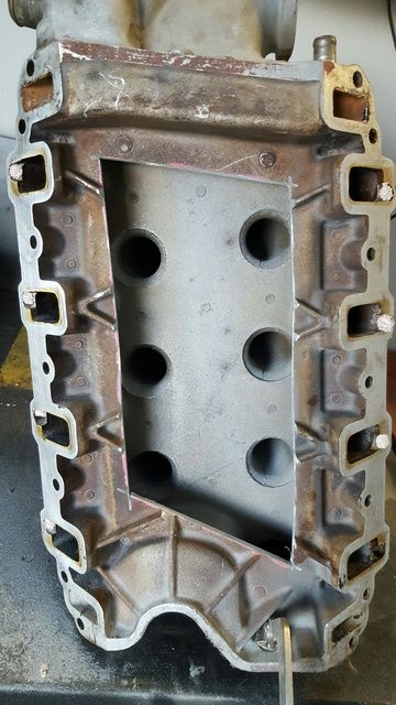
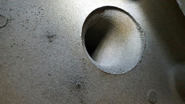
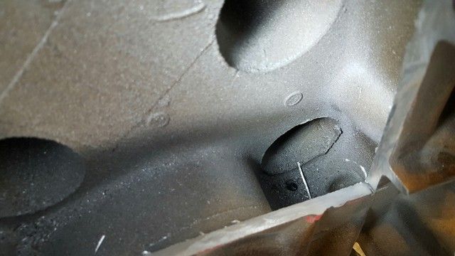
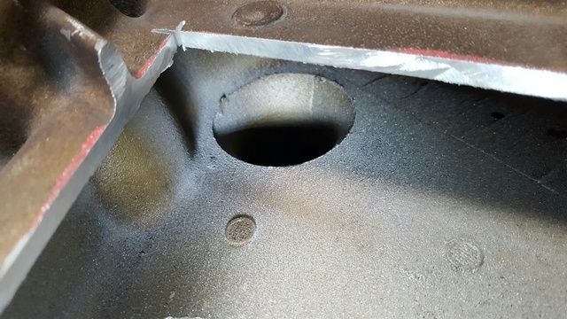
January 6, 2017 at 9:17 am #21363Had a ten minute play last night. Hit the top surface with the flap disc to get rid of the casting flash, then used an aluminium carbide to smooth the entry out. I’ll need to get some long shank cutters though, as well as a hone of some sort around 42mm dia.
Top image is flap disc only, bottom image is initial work. Hard to tell in the pictures but its much better.
January 5, 2017 at 2:03 pm #21354Yeah that car’s a winner.
January 5, 2017 at 11:17 am #21351Alright, let’s start the new year off.
No major progress but I intend on trying to get out to the garage at least an hour a night to slowly chip away at some of the tasks needed. Just after Christmas I went up to the old man’s place and came back with a trailer full of parts off the VQ. I have the engine on the stand in the shed, as well as a bunch of other bits (Programmable ECU, Crane Hi-6, Bolt ons etc.).
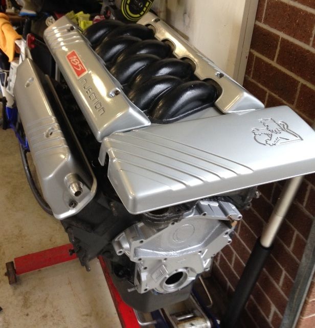
Have started with the top of the engine and will work my way down. Going with a banana manifold for this engine, as I have a strange love for the factory top end look. (Insert Cava hate
 ). I could ramble on for ages about crazy plans to reduce heat soak but I’m not sure if I’ll even go that far yet so I will hold fire.
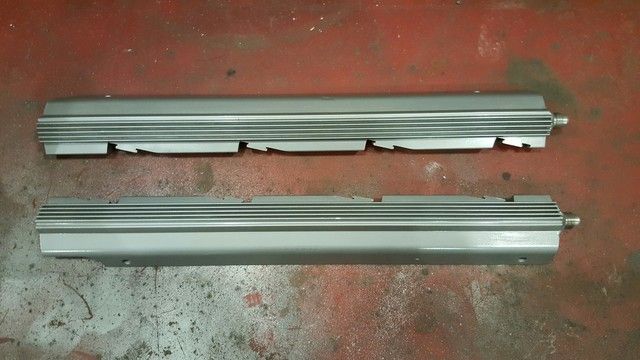
So I dug through the collection of engine covers, manifolds, throttle bodies and fuel rails and settled on a set of 185i covers from a VR I had, a 70mm TB, a set of VR/VS rails and the cleanest set of bananas from the fruit shop I have apparently amassed. Welded on some -6 fittings to the rail, plan to use the factory cross over pipe under the covers. Stripped and repainted the covers. Stripped, welded on -10 fittings and repainted the rocker covers. Also went hell for leather on the bananas.
Nasty little lips on the runner inlets.
Cylinder 8 is a little challenging to get to without cutting more out. I’ll give it a go as is first.
This is as good as it gets for Cylinder one due to the water jacket.
December 15, 2016 at 10:58 am #21051December 14, 2016 at 3:48 pm #21038OK so basically nothing has changed on this since May (wow, 6 months?).
As in the other thread I no longer have the VQ so this now has a full time garage spot. In the interim I’ve managed to spend almost all of our spare cash on finishing the house. I’m now almost done.
And now I want to finally get my bike (MT-07) so it may still be a while for real work to start on this!
So I did some important things like detailing the car and refurbishing my 185i engine covers I’ve had stashed for years along with some rocker covers. Ground breaking stuff.
Next step will be to pull the engine from the VQ, give it a little bit of love, then put it into the VN with bananas on it and a T5 behind it. VN needs a 3.45 Trutrack diff built as well. Bananas will be prepped (cut open, ports blended and work the elbow with a 70mm TB) and I’ll put in a Crow 4503 cam (227/220 on 113) which looks to me like a great turbo cam with the bananas.
Hope to crack into this during winter so I stop being ‘all talk’. However I don’t think much will happen until I get the bike…
December 14, 2016 at 3:27 pm #21037So in the end I dropped this to my old man’s place on his birthday at the start of November. He then took it on a few organised cruises, now it’s been parked up waiting for me to pull the parts off it I need.
I’ve almost finished a cradle to transport the engine from his place to mine. Then basically that’s the end of the book for me on this ride.
Looks like he will run it with a stock engine and baby cam, with the built 4k stalled auto and 4.11’s behind it.
December 8, 2016 at 8:47 am #20937As posted on Inj5L FB Page, a crows foot attachment is the only way.
Suggest for your own sanity that you replace the hard lines with braided items. It means you can drop the trans and undo the lines as they are flexible, rather than fighting for hours with the trans in place.
November 23, 2016 at 1:34 pm #20710Nice one!!
November 23, 2016 at 1:26 pm #20709Great stuff.
That’s a lot of a$$ crack lol
November 4, 2016 at 2:14 pm #20441I wouldn’t think the manifolds should be that hot if you really are just cruising around. It will always look worse at night but it might be worth checking to see the timing isn’t retarded for some reason.
November 3, 2016 at 4:15 pm #20431Nah they should all have 2. Instead of it going to the intank return line and check valve. I’ve just made my own.
Maybe it’s just early tanks, but mine have always had the return line integral to the tank itself…
November 2, 2016 at 3:32 pm #20423So you added the second line to the tank bulkhead? The pump carriers I’ve seen only have one hose connection.
October 27, 2016 at 12:10 pm #20349I’m surprised that with all the suspension gear you have on it, it doesn’t feel pretty good.
It may be that the expectations need to be managed by keeping in mind that it is a 20yr old commodore
 October 25, 2016 at 1:13 pm #20323
Was asking purely to do away with having to buy a manifold and heads. Wondering if there would be a measurable difference or not And then to add to the first post, how it would behave once a turbo is included in the setup, like compound boost. And would having a larger plenum under the blower affect intake temps at all? Or would a cooler still be required?
Have a solid think about the questions you’re asking first before I start typing out more information….
October 24, 2016 at 4:12 pm #20306Gary,
I think your first port of call is a wheel alignment. Something a little more suited to your application, not just a ‘minimise tyre wear’ approach.
October 21, 2016 at 8:21 am #20254Ok I’ll elaborate.
The reason for longer runners is due to resonance within the pipe during airflow. In naturally aspirated form, when the airflow hits a harmonic the resistance to flow is mildly reduced, which assists the charge air making its way into the cylinder.For example, on my manifold I have a 10″ runner from bellmouth to valve head. This should give a 2nd order harmonic at about 5000rpm. This is longer than the 8″ runner on a VN Group A manifold (of which I replicated the plenum and general layout) which has the same harmonic a bit over 6000rpm. For a street engine the longer runner works better for my application. The longer the runner, the lower rpm the 2nd order harmonic occurs at. The higher the order the harmonic, the less impact it has (1st order is stronger than 2nd etc.)
Boosted engines have no need for these effects as the air is being forced in so the gain from a harmonic is negligible. The only reason to run a some length of ‘runner’ is to try and reduce the turbulence in the runner for more effective cylinder fill.
For more reading, look up ‘Standing Waves’ or ‘Harmonics’.
October 21, 2016 at 8:14 am #20253No.
-
This reply was modified 7 years, 10 months ago by
-
AuthorPosts

