Forum Replies Created
-
AuthorPosts
-
July 19, 2016 at 5:16 pm #18586
ImmortalityParticipant- 97 HSV Senator 185i 02 VX L67 Calais
View build HERE
Posts: 535Hey Gary, i have a VZ cradle at home and VS control arms which bolt together perfectly, both cradles are almost identical in shape, the VS is just a little narrower.

Does that mean the later model arms are the same the as the VS?
I was under the impression that the VZ arms have slightly different angles to help with the suspension geometry through it’s full range of motion. It would also be a bonus to have the later model hand brake and later model rear brakes as a starting point.
July 18, 2016 at 1:19 pm #18537
ImmortalityParticipant- 97 HSV Senator 185i 02 VX L67 Calais
View build HERE
Posts: 535Even now Vizard the Wizard is still at the forefront of engine development.
Many moons ago I worked with an engineer who built and raced Mini’s using Vizards know how, he won his class (classics) each year and almost won outright against the open class cars. The man has beat many a V8 around the Pukekohe race track.
July 16, 2016 at 6:18 pm #18489
ImmortalityParticipant- 97 HSV Senator 185i 02 VX L67 Calais
View build HERE
Posts: 535Yeah spacer will definitely fix it
 July 16, 2016 at 5:11 pm #18481
ImmortalityParticipant- 97 HSV Senator 185i 02 VX L67 Calais
View build HERE
Posts: 535Hey,
Not sure if you are aware but there seems to be an issue with the CRD throttle body on a DP style manifold with the IAC/ MAP sensor cavity been blocked off.
Check this thread for info http://www.aussiev8.com.au/holden-v8s/68922-vs-clubsport-304-full-rebuild.html#post718977 and how to fix.
July 15, 2016 at 7:07 pm #18469
ImmortalityParticipant- 97 HSV Senator 185i 02 VX L67 Calais
View build HERE
Posts: 535but it’s only air. Won’t the engine only use what it can take. Efi is dry induction compared to carby
..And there lay another problem – the size of most throttle bodies are 1000cfm and more which is way too big for a 304 or 355. Even with 100% VE, a 355 turning at 7500 rpm only requires a TB that flows 770cfm. This reduces air speed and makes less torque in the mid-range. 1000cfm with 100% is nearing 10,000rpm CRD Engineering make a 750cfm TB which is a great match for a well tuned 355.
Well then a dual plane that only sees half the flow (per bank) should be ideal then

I had toyed with the idea of a single plane and then fitting a plenum divider which I think is fairly much what the Duggan manifold is (Smitty uses on his VK racer).
At the end of the day I know that this manifold, with standard 304 heads, 10:1 comp and a small solid FT cam will make 400hp (basic NZV8 tourer specs).
-
This reply was modified 8 years, 4 months ago by
Immortality.
July 15, 2016 at 5:39 pm #18463
ImmortalityParticipant- 97 HSV Senator 185i 02 VX L67 Calais
View build HERE
Posts: 535David Vizard, Engine genius.
I’ve read some of his books, really wanted to go to his seminar when he was here in NZ but things just didn’t work out right.
July 15, 2016 at 4:49 pm #18461
ImmortalityParticipant- 97 HSV Senator 185i 02 VX L67 Calais
View build HERE
Posts: 535Comes down to application I guess, some people say the single plane is king but when someone like TK on the AV8 forum uses a dual plane on a 365 cu race engine that shows me it can’t be all bad. Some other guy from the US says something similar and he’s kinda like the engine guru of engine guru’s…..
July 15, 2016 at 4:35 pm #18460
ImmortalityParticipant- 97 HSV Senator 185i 02 VX L67 Calais
View build HERE
Posts: 535Very tidy
 July 15, 2016 at 4:32 pm #18458
ImmortalityParticipant- 97 HSV Senator 185i 02 VX L67 Calais
View build HERE
Posts: 535I didn’t know what milling it actual achieved, so good to know now. Just new it helped in some cases. Esp in some SBC
In a normal Dual plane manifold each intake port only see half of the total volume of the TB so if you have a 1000cfm TB than each port only “sees” 500cfm of flow with a small plenum volume which promotes good airspeed at low throttle openings but limits flow at full throttle.
If you mill down the divider each runner can now draw on the full 1000cfm of flow as well as increasing the plenum volume. There is also stuff with intake pulses pulling on opposite runners, gets quiet technical and I don’t understand it all either.
July 15, 2016 at 1:15 pm #18449
ImmortalityParticipant- 97 HSV Senator 185i 02 VX L67 Calais
View build HERE
Posts: 535LOL, yep it’s not even bolted on yet. We will check bank to bank fuelling but that is a long way off yet. Car needs to be on the road by the start of October if my job application goes well.
Car will be primarily road tuned (as I have all the gear hear for that) but it may spend a little time on the rollers as well so we may possibly run it with/without spacer to see if there is any difference as I will have a spacer. I also have a NOS big shot kit which uses a 1/2 open spacer which may get fitted at some stage too

edit: I know of another engine that had a large AFR discrepancy between banks, it had a full twin exhaust system, once they fitted a balance pipe into the system the banks balanced out (was a cammed up 304, with head work but still running banana’s).
-
This reply was modified 8 years, 4 months ago by
Immortality.
-
This reply was modified 8 years, 4 months ago by
Immortality.
July 15, 2016 at 1:06 pm #18446
ImmortalityParticipant- 97 HSV Senator 185i 02 VX L67 Calais
View build HERE
Posts: 535To do it correctly requires marking out the ports and then transferring marks over to the manifold and comparing. In this case I just put it in place noted the position on the intake gaskets and fitment in the valley and then removed the manifold and checked it against the gaskets. Good enough as I’m not port matching but if you were then marking it out is the only real way. Some pics from HPE (on the AV8 forum) showing his port matching work.

 July 15, 2016 at 11:47 am #18441
ImmortalityParticipant- 97 HSV Senator 185i 02 VX L67 Calais
View build HERE
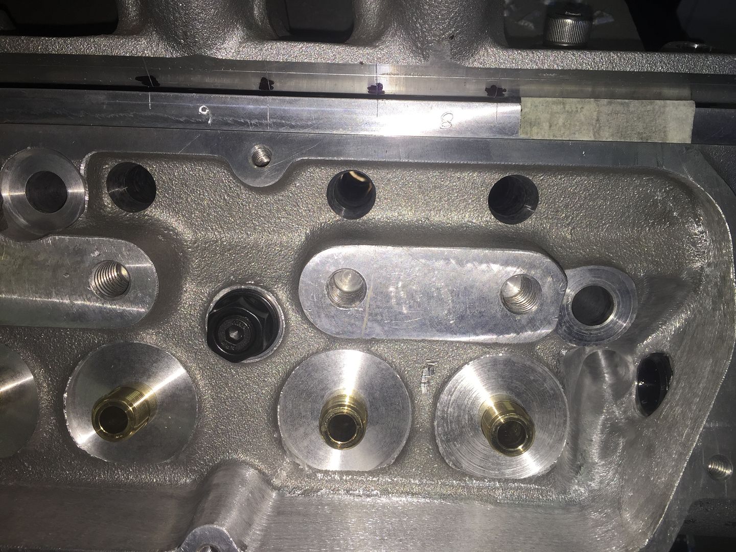
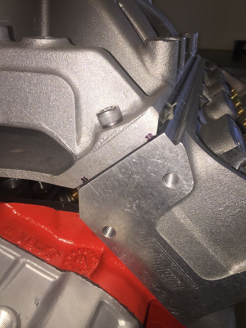
Posts: 535Did a quick fitment check today before the manifold goes off to the machinist, port alignment looks reasonably good. Those NZV8’s can’t have had much machined off the heads.
Attachments:
You must be logged in to view attached files.July 14, 2016 at 6:44 pm #18425
ImmortalityParticipant- 97 HSV Senator 185i 02 VX L67 Calais
View build HERE
Posts: 535Sorry for late reply guys ended up going with the bosch green 42’s was told for the setup they were the minimum. Seems to be running fine so far so fingers crossed.

Have you checked your AFR ?
I would imagine it has been tuned to suit with these injectors ( I highly doubt anybody would do a mail order tune for something like this)? Assuming so I have no doubt the tuner would have mentioned it if they weren’t up to the task.
Having said that, it can’t hurt to ask the tuner what the max injector duty cycle is, a dyno graph should probably have the AFR’s on it too.
July 11, 2016 at 7:12 pm #18354
ImmortalityParticipant- 97 HSV Senator 185i 02 VX L67 Calais
View build HERE
Posts: 535I wonder if anybody has ever done a comparison between the Harrop and TP DP manifolds?
July 11, 2016 at 5:34 pm #18349
ImmortalityParticipant- 97 HSV Senator 185i 02 VX L67 Calais
View build HERE
Posts: 535I’m probably going to go with a 1/2″ open spacer which should achieve the same result, seeing as this manifold is slightly lower than a TP low dual it should still fit without issue. With a spacer on top I should also be able to blend a nice radius into the top runners which was the original reason for fitting it.
July 11, 2016 at 4:44 pm #18347
ImmortalityParticipant- 97 HSV Senator 185i 02 VX L67 Calais
View build HERE
Posts: 535Yes, it will be getting some HPC treatment. Contemplating doing the top in a black wrinkle type coating but have the Harrop name plate done in gloss black.
Hope to have it at the machine shop later this week to get the injector boss’s machined to suit.
July 10, 2016 at 6:57 pm #18328
ImmortalityParticipant- 97 HSV Senator 185i 02 VX L67 Calais
View build HERE
Posts: 535As far as I’m aware all Commodores VB- VZ (except the 4 cyl models) used a 5 x 120 PCD with 69.5mm centre bore size. Not sure about offsets though as they changed through the various models. There was a thread on the SC forum which listed all the various offsets through the models.
This website is good if you know your original wheel size/offset to workout what should or shouldn’t fit
-
This reply was modified 8 years, 4 months ago by
Immortality.
July 10, 2016 at 1:37 pm #18320
ImmortalityParticipant- 97 HSV Senator 185i 02 VX L67 Calais
View build HERE
Posts: 535OK, so the main part of the swap is now in my possession

I’ve been trying to figure out what the 2 hollow posts next to the centre bolt holes were and it looks like the manifold was cast with a heat cross-over for engine coolant rather than an exhaust cross-over the early type pollution manifolds had, this of course isn’t much use to us however underneath the manifold there are 2x 20mm grub screws in said passage which got me thinking I can use this as a valley breather setup instead

Looks like whom ever had this manifold before had it coated in something so there is no corrosion anywhere neither has it had any porting work done so it is very much a virgin manifold in many respects

edit: forgive the shitty phone pics
-
This reply was modified 8 years, 4 months ago by
Immortality. Reason: add pics
-
This reply was modified 8 years, 4 months ago by
Immortality.
Attachments:
You must be logged in to view attached files.July 4, 2016 at 5:43 pm #18154
ImmortalityParticipant- 97 HSV Senator 185i 02 VX L67 Calais
View build HERE
Posts: 535It definitely is a nice work lamp. Nothing worse than working on a car in the garage with great lighting only to be working in the shadows because of the bonnet.
July 4, 2016 at 4:38 pm #18143
ImmortalityParticipant- 97 HSV Senator 185i 02 VX L67 Calais
View build HERE
Posts: 535That engine bay shot has given me a few ideas cava, I like the overflow/catch can setup you have there I think I’m gonna have to do something similar. thanks for the link immortality, it’ll be a while till I get to swap my manifold but at least I know what I need and where to get the bits I want
With the airbox gone from the factory position it does open up a lot of opportunities to utilise that space

-
AuthorPosts

